Setting up Clion with Raspbery Pico Development and Adding a GPIO Interrupt.
In this quick guide we go over getting CLion to play nice with the raspberry pi-pico ecosystem and then show the code example to setup a basic GPIO interrupt.

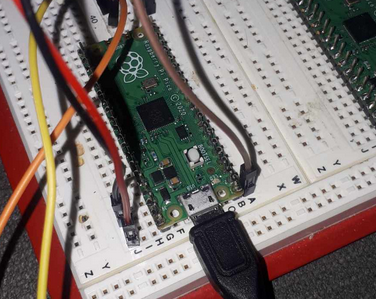
In the last guide we covered the very basic console level access to develop for the RPi2040. One will still need most of that guide and it's example ecosystem example in order to ensure they can see if the chip loaded to the USB bus, the .uf2 file loaded, and if printf is enabled by the USB message of /dev/ttyACM0 - so please do review it.
Update - Stepping Debugging is now working! If you need it here is a guide!
 thinkmeltprotonmail.com
- Getting Clion to work with pico-sdk
- Clion is a powerful complex and comprehensive development IDE.
- Getting it to work / play with rasbperry pi-pico can be problematic.
- Standalone console mode coding with your own CMakeLists.txt will not effectively work, you need the CMakeLists.txt from the pico-examples.
- Install your pico-sdk
git clone https://github.com/raspberrypi/pico-sdk.git
cd pico-sdk
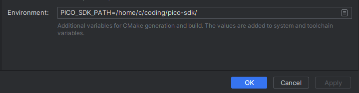
git submodule update --init2. Export your path for it.
export PICO_SDK_PATH=/home/where/lives/pico-sdk3. Next download and install the examples
git clone https://github.com/raspberrypi/pico-examples.git- You can safely open the pico-examples folder:
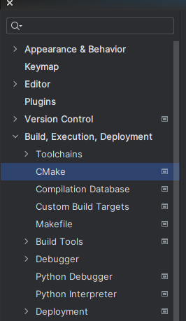
- Inside the project settings set your CMake:
- CLion will index the project and hopefully your commands will be guided-enabled:
- Note you cannot do stepping debugging yet because this code doesn't run on the CPU, it will run on the Raspberry Pico CPU. You might want to consider a JTAG Diagnostic Level tool if you are getting serious (or with the roll-your-own option!)
Adding your own Custom Project:
- We want to take example code 'blink' and extend it to 'blink2'
- Open the main CMakeLists.txt of the main pico-examples and amend as:
- You will notice all the subprojects extend out from this like a tree with many sub-module CMakeLists.txt
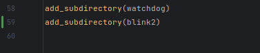
Next we cp blink to blink2
cp -R blink blink2We next amend the CMakeLists.txt for the blnk2 setup - adding in options for USB output as in:
add_executable(blink2 blink.c)

# pull in common dependencies
target_link_libraries(blink2 pico_stdlib)

# create map/bin/hex file etc.
pico_add_extra_outputs(blink2)

# add url via pico_set_program_url
example_auto_set_url(blink2)

pico_enable_stdio_usb(blink2 1)
pico_enable_stdio_uart(blink2 0)
And then we make our code as in:
/**
* Copyright (c) 2020 Raspberry Pi (Trading) Ltd.
*
* SPDX-License-Identifier: BSD-3-Clause
*/
#include <stdio.h>
#include "pico/stdlib.h"
#include "hardware/gpio.h"
void gpio_callback(uint gpio, uint32_t events)
{
const uint LED_PIN = PICO_DEFAULT_LED_PIN;
uint32_t time_now;
if (gpio==0)
{
time_now = time_us_32();
printf("GPIO:0 Activated: %d\n", time_now);
}
if (gpio==1)
{
printf("GPIO:1 Activated at clock\n");
}
}
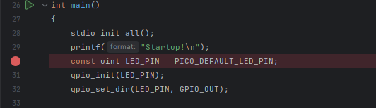
int main()
{
stdio_init_all();
printf("Startup!\n");
const uint LED_PIN = PICO_DEFAULT_LED_PIN;
gpio_init(LED_PIN);
gpio_set_dir(LED_PIN, GPIO_OUT);
gpio_init(0);
gpio_set_dir(0, GPIO_IN);
gpio_init(1);
gpio_set_dir(1, GPIO_IN);
gpio_set_irq_enabled_with_callback(0, GPIO_IRQ_EDGE_RISE | GPIO_IRQ_EDGE_FALL, true, &gpio_callback);
gpio_set_irq_enabled(1, GPIO_IRQ_EDGE_RISE | GPIO_IRQ_EDGE_FALL, true);
//gpio_set_irq_enabled_with_callback(1, GPIO_IRQ_EDGE_RISE | GPIO_IRQ_EDGE_FALL, true, &gpio_callback);
while (true)
{
sleep_ms(250);
printf("Test push\n");
}
}
Going over the code:
- We have enabled a single generalized call-back from:
gpio_set_irq_enabled_with_callback(0, GPIO_IRQ_EDGE_RISE | GPIO_IRQ_EDGE_FALL, true, &gpio_callback);- It is saying if GPIO0 goes from high-to-low, or low-to-high we want it to call the fuction gpio_callback:
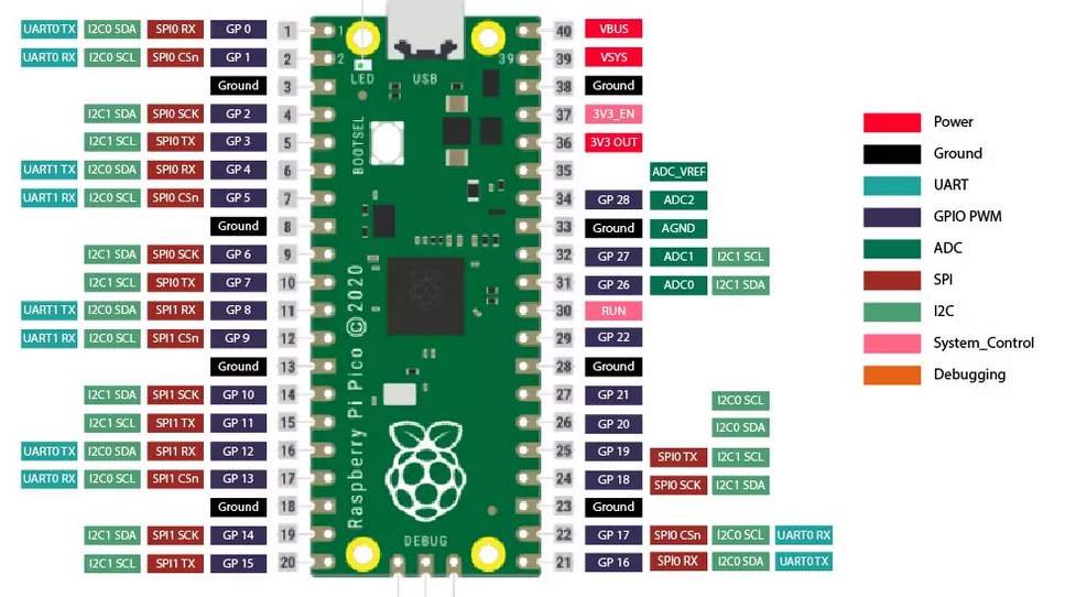
- Don't confuse PAD numbers with GPIO numbers. GPIO0 is where you hook your wire and where results will show up.
- Interrupts are critical to master. We either have the computer constantly checking and polling the pin for a change - or we simply have the Interrupt activated when something occurs. If we are going to get any kind of multi-tasking we need interrupts!
Inside our callback an example is as:
void gpio_callback(uint gpio, uint32_t events)
{
  uint32_t time_now;
  if (gpio==0)
  {
    time_now = time_us_32();
    printf("GPIO:0 Activated: %d\n", time_now);
  }
  if (gpio==1)
  {
    printf("GPIO:1 Activated \n");

  }
}
The second (gpio==1) can be checked for multiple interrupts allowing for multiple pin monitoring and our main body sets the additional hook as in:
gpio_set_irq_enabled(1, GPIO_IRQ_EDGE_RISE | GPIO_IRQ_EDGE_FALL, true);Once you have it all loaded (use this tutorial for loading your .uf2 file)
Any time you get a transition (even a glitchy noise one) you will see output as in:
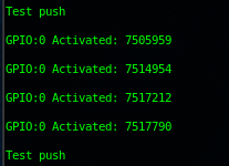
uint32_t time_now;- Sets a 32-bit unsigned integer;
time_now = time_us_32();- Will get the current offset clock in microseconds.
Summary:
We need Clion or other IDE development systems for power enhancing productivity such as code folding etc. If you have produced in an IDE going back is almost crippling. We also need to master interrupts right out of the gate if we are going to do anything powerful at all and enable multi-tasking. Once you can handle interrupts you can get these chips to do a lot of things concurrently.