RaspBerry Pi Pico C Example Code Reference
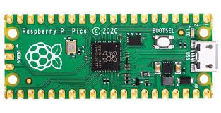
We give various Coding Examples for the Raspberry Pi Pico

Here are clear, well-structured examples and explanations for the Raspberry Pi Pico (RP2040) using the official C/C++ SDK. All examples assume a standard Pico board and the Pico SDK setup (including pico_stdlib.h, appropriate CMakeLists.txt configuration, etc.).
1. GPIO pin high/low at 1 ms intervals (simple blink example)
This program toggles a GPIO pin (e.g., the onboard LED on GP25) every 1 millisecond.
#include <stdio.h>
#include "pico/stdlib.h"

int main() {
    const uint gpio_pin = 25;           // Onboard LED (change as needed)

    stdio_init_all();                   // Optional: for potential debug output

    gpio_init(gpio_pin);
    gpio_set_dir(gpio_pin, GPIO_OUT);

    while (true) {
        gpio_put(gpio_pin, 1);          // Set high
        sleep_ms(1);
        gpio_put(gpio_pin, 0);          // Set low
        sleep_ms(1);
    }

    return 0;
}
Note: sleep_ms(1) provides millisecond-resolution delay using the SDK timer.
2. Read ADC 20 times per second and append to a file
The RP2040 ADC supports up to ~500 ksps in optimal conditions, so 20 samples per second is easily achievable. However, the Pico lacks a built-in filesystem in bare-metal C SDK mode. File appending typically requires adding an SD card library (e.g., no-OS-FatFS-SD-SPI-RPi-Pico) or redirecting output via USB serial for logging on a host PC.
For demonstration, this example reads ADC0 (GP26) at 20 Hz and prints values over USB serial (visible in a terminal like PuTTY or minicom at 115200 baud). You may replace printf with file-write code if an SD card is attached.
#include <stdio.h>
#include "pico/stdlib.h"
#include "hardware/adc.h"

int main() {
    stdio_init_all();                   // Enables USB CDC serial for printf

    adc_init();                         // Initialize ADC (default 48 MHz clock)
    adc_gpio_init(26);                  // Use GPIO26 / ADC0
    adc_select_input(0);                // Select ADC channel 0

    while (true) {
        uint16_t result = adc_read();   // 12-bit value (0–4095)

        printf("ADC0: %u\n", result);

        sleep_ms(50);                   // 50 ms = 20 Hz
    }

    return 0;
}
CMakeLists.txt addition (required for USB serial output):
pico_enable_stdio_usb(your_project_name 1)
pico_enable_stdio_uart(your_project_name 0)
If file storage is essential, integrate an SD card library and use fprintf to a FILE* stream.
3. PWM example with 5 different duty cycles
This example configures PWM on GPIO16 (slice 8, channel A) at approximately 1 kHz and cycles through five duty cycles: 0%, 25%, 50%, 75%, and 100%.
#include <stdio.h>
#include "pico/stdlib.h"
#include "hardware/pwm.h"

int main() {
    const uint pwm_pin = 16;            // GPIO16 supports PWM
    gpio_set_function(pwm_pin, GPIO_FUNC_PWM);

    uint slice_num = pwm_gpio_to_slice_num(pwm_pin);
    uint chan = pwm_gpio_to_channel(pwm_pin);

    // Set frequency ~1 kHz (system clock 125 MHz default)
    // wrap = (125e6 / freq) - 1 → wrap ≈ 124999 for 1 kHz
    pwm_set_wrap(slice_num, 124999);
    pwm_set_clkdiv(slice_num, 1.0f);    // No division

    pwm_set_enabled(slice_num, true);

    const float duties[] = {0.0f, 25.0f, 50.0f, 75.0f, 100.0f};

    while (true) {
        for (int i = 0; i < 5; i++) {
            uint16_t level = (uint16_t)((duties[i] / 100.0f) * 125000.0f);
            pwm_set_chan_level(slice_num, chan, level);

            printf("Duty cycle: %.0f%%\n", duties[i]);
            sleep_ms(2000);             // Hold each duty for 2 seconds
        }
    }

    return 0;
}
Note: For cleaner frequency/duty control, helper functions like those in community examples can compute wrap and level values more flexibly.
4. Output to serial port (USB CDC or UART)
The most common method uses USB CDC (appears as a virtual COM port on the host PC). The SDK redirects stdio (printf/scanf) to USB when enabled.
#include <stdio.h>
#include "pico/stdlib.h"
#include "hardware/uart.h"

int main() {
    stdio_init_all();                   // Initializes USB CDC stdio

    // Optional: also initialize UART0 on GP0/GP1 at 115200 baud
    uart_init(uart0, 115200);
    gpio_set_function(0, GPIO_FUNC_UART);
    gpio_set_function(1, GPIO_FUNC_UART);

    uint counter = 0;

    while (true) {
        // Output to USB serial (most common)
        printf("USB CDC: Counter = %u\n", counter);

        // Output to physical UART0 (if connected to another device)
        uart_puts(uart0, "UART0: Counter = ");
        char buf[16];
        sprintf(buf, "%u\n", counter);
        uart_puts(uart0, buf);

        counter++;
        sleep_ms(1000);
    }

    return 0;
}
CMakeLists.txt (for USB output):
pico_enable_stdio_usb(your_project_name 1)
pico_enable_stdio_uart(your_project_name 0)   // or 1 if you prefer UART stdio
5. Explanation of clocks and example program to read them
The RP2040 features a flexible clock tree with several key domains:
- clk_ref — Reference clock (typically 12 MHz from XOSC crystal, or fallback to ROSC ~6–12 MHz).
- clk_sys — Main system clock for Cortex-M0+ cores, SRAM, most peripherals (default 125 MHz, max 133 MHz via PLL).
- clk_peri — Peripheral clock for UART, SPI, I2C, PWM (usually follows clk_sys or can use clk_usb/ADC 48 MHz).
- clk_usb — Fixed 48 MHz for USB (from PLL).
- clk_adc — Fixed 48 MHz for ADC (from PLL).
- ROSC — Internal ring oscillator (~6–12 MHz, variable with temperature/voltage).
- XOSC — External crystal oscillator (12 MHz nominal).
- PLL sys and PLL usb — Phase-locked loops generating higher/fixed frequencies.
Use clock_get_hz(enum clock_index clk_index) from hardware/clocks.h to read frequencies.
Example program:
#include <stdio.h>
#include "pico/stdlib.h"
#include "hardware/clocks.h"

int main() {
    stdio_init_all();

    while (true) {
        uint32_t clk_ref_hz  = clock_get_hz(clk_ref);
        uint32_t clk_sys_hz  = clock_get_hz(clk_sys);
        uint32_t clk_peri_hz = clock_get_hz(clk_peri);
        uint32_t clk_usb_hz  = clock_get_hz(clk_usb);
        uint32_t clk_adc_hz  = clock_get_hz(clk_adc);

        printf("clk_ref  = %u Hz\n", clk_ref_hz);
        printf("clk_sys  = %u Hz\n", clk_sys_hz);
        printf("clk_peri = %u Hz\n", clk_peri_hz);
        printf("clk_usb  = %u Hz\n", clk_usb_hz);
        printf("clk_adc  = %u Hz\n", clk_adc_hz);

        printf("-------------------\n");
        sleep_ms(2000);
    }

    return 0;
}
Typical default output (on stock Pico):
- clk_ref ≈ 12 000 000 Hz
- clk_sys ≈ 125 000 000 Hz
- clk_peri ≈ 125 000 000 Hz
- clk_usb = 48 000 000 Hz
- clk_adc = 48 000 000 Hz
These functions provide runtime verification of clock configuration.
Let me know if you require modifications, such as using interrupts, DMA, or alternative pin assignments.