Full Diagnostic Software for your NRF24L01 Projects!
We Inspect Grok 4's Ability to Write a Full Diagnostic Software for the NRF24L01 RF chip

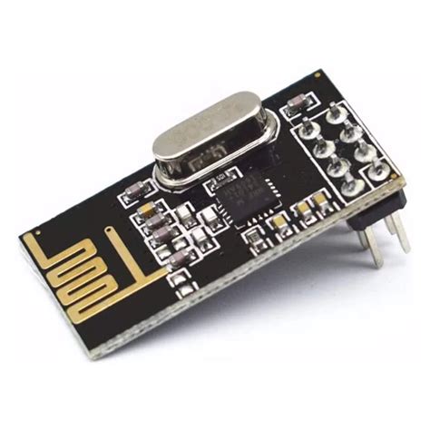
NRF24L01 is an amazing communications chip developed by Nordic Semiconductor. However it did have some issues.
- It is a 3.3V powered device.
- When it transmits it can hammer the power pin with current demand knocking out it's own power supply, often you have to put a power buffering capacitor in place, which was discovered on long packet sends.
- It is subject to noise to alleviate this, many twist up the MISO/MISO pins.
Rerequisites: You will need to install all your essentials,
sudo apt install wiringpi libgpiod build-essentialYou will also need to enable your raspberry SPI,
sudo raspi-config- Enable SPI bus and reboot.
You should be able to see your SPI devices.
c@c:~/c_software/spi_diagnostics $ ls /dev/ | grep spi
spidev0.0
spidev0.1
A Wiring Primer.
GND - Ground
VCC - 3.3V (Note don't hook to 5V it can fry these chips)
CE - Chip Enable. Will put the chip into different modes we outline below
CSN - Chip Select Node. If you have multiple devices on a SPI bus, this determines that you are talking to it.
SCK - Source Clock. Use this to set clock edge bits.
MISO - Master in Slave Out (Where the end device communicates back to the Raspberry Pi Zero
MOSI - Master Out Slave In (Where the Raspberry Pi Zero communicates to the nrf24L01.
Can we Just Wire CE to High? Yes and No..
Behavior When CE Is Held High
According to the nRF24L01 Product Specification:
- In RX (Primary Receiver) mode (PRIM_RX = 1 in CONFIG register, PWR_UP = 1): The module continuously listens for incoming packets. This is the standard and recommended way to operate a receiver. No pulsing of CE is required.
- In TX (Primary Transmitter) mode (PRIM_RX = 0):
- If the TX FIFO contains data when CE goes high (or is already high), the module begins transmitting the packet(s).
- After successful transmission (and any auto-acknowledgments/retransmissions), if CE remains high and the TX FIFO is now empty, the module enters Standby-II mode (a low-power idle state with the crystal oscillator running).
- To transmit the next packet, you simply write a new payload to the TX FIFO via SPI. The module will automatically start transmitting it because CE is already high.
- This eliminates the need to pulse CE for every transmission.
Key point: Leaving CE high works for both continuous reception and “fire-and-forget” transmission once the initial setup is complete. You do not need to toggle CE for each packet in many common use cases.
Wiring and Pinout Explanation for Raspberry Pi Zero and nRF24L01
The Raspberry Pi Zero uses the BCM2835/2837 System-on-Chip (SoC) and exposes SPI0 as the primary SPI interface (device node /dev/spidev0.0). This is the SPI channel used by the diagnostic software below. SPI0 operates at a default clock speed of 1 MHz in the provided code, which is well within the nRF24L01+ specification (maximum 10 MHz).
Before running any code:
- Enable SPI via
sudo raspi-config→ Interface Options → SPI → Yes, then reboot. - Install the wiringPi library if not already present (
sudo apt install wiringpi).
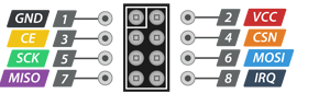
nRF24L01+ Physical Pinout (viewed from the top of the module with the antenna/PCB edge oriented away from you; pins are numbered left-to-right):
| Pin | Name | Direction | Description |
|---|---|---|---|
| 1 | GND | – | Ground |
| 2 | VCC | Power | 1.9–3.6 V (strictly 3.3 V from Pi) |
| 3 | CE | Input | Chip Enable (TX/RX activation) |
| 4 | CSN | Input | SPI Chip Select (active-low) |
| 5 | SCK | Input | SPI Serial Clock |
| 6 | MOSI | Input | SPI Master-Out/Slave-In |
| 7 | MISO | Output | SPI Master-In/Slave-Out |
| 8 | IRQ | Output | Interrupt (optional – left unconnected) |
Complete Wiring to Raspberry Pi Zero 40-pin Header (using physical pin numbers):
- nRF24L01 VCC (pin 2) → Pi physical pin 1 or 17 (3.3 V)
- nRF24L01 GND (pin 1) → Pi physical pin 6, 9, 14, 20, 25, 30, 34 or 39 (GND)
- nRF24L01 CE (pin 3) → Pi BCM GPIO 17 (physical pin 11)
- nRF24L01 CSN (pin 4) → Pi BCM GPIO 8 (physical pin 24) – this is the hardware SPI0 CE0 line automatically managed by the kernel SPI driver
- nRF24L01 SCK (pin 5) → Pi BCM GPIO 11 (physical pin 23) – SPI0 SCLK
- nRF24L01 MOSI (pin 6) → Pi BCM GPIO 10 (physical pin 19) – SPI0 MOSI
- nRF24L01 MISO (pin 7) → Pi BCM GPIO 9 (physical pin 21) – SPI0 MISO
- nRF24L01 IRQ (pin 8) → not connected (diagnostic code uses polling)
Important notes:
- Power the module from the Pi’s 3.3 V rail only; 5 V will destroy it.
- Add a 10 µF electrolytic capacitor across VCC/GND close to the module for stability.
- The SPI driver automatically asserts/de-asserts CSN (GPIO 8) during each transfer; no manual GPIO control of CSN is required in the code.
1. Ping Communications Check Software (nrf24_ping.c)
This program verifies basic SPI communication, register read/write capability, and successful packet transmission on the nRF24L01 attached to the Raspberry Pi Zero. It configures the module as a transmitter, sends a 4-byte test payload, and confirms the TX_DS flag is set in the STATUS register.
#include <stdio.h>
#include <stdlib.h>
#include <unistd.h>
#include <wiringPi.h>
#include <wiringPiSPI.h>
#include <stdint.h>

#define CE_PIN   17          // BCM GPIO 17 (physical pin 11)
#define SPI_CH   0           // SPI channel 0 (/dev/spidev0.0)
#define SPI_SPEED 1000000    // 1 MHz

static void nrf_write_reg(uint8_t reg, uint8_t val) {
    uint8_t buf[2] = {0x20 | reg, val};
    wiringPiSPIDataRW(SPI_CH, buf, 2);
}

static uint8_t nrf_read_reg(uint8_t reg) {
    uint8_t buf[2] = {reg, 0xFF};
    wiringPiSPIDataRW(SPI_CH, buf, 2);
    return buf[1];
}

static void nrf_write_multi(uint8_t reg, const uint8_t *data, uint8_t len) {
    uint8_t buf[6] = {0};               // max address = 5 bytes + command
    buf[0] = 0x20 | reg;
    for (uint8_t i = 0; i < len; i++) buf[1 + i] = data[i];
    wiringPiSPIDataRW(SPI_CH, buf, 1 + len);
}

int main(void) {
    if (wiringPiSetupGpio() == -1) {
        fprintf(stderr, "wiringPi GPIO setup failed.\n");
        return 1;
    }
    if (wiringPiSPISetup(SPI_CH, SPI_SPEED) == -1) {
        fprintf(stderr, "SPI setup failed.\n");
        return 1;
    }

    pinMode(CE_PIN, OUTPUT);
    digitalWrite(CE_PIN, LOW);

    printf("nRF24L01 Ping Diagnostic (Raspberry Pi Zero)\n");
    printf("============================================\n");

    // Basic SPI sanity check
    uint8_t status = nrf_read_reg(0x07);
    printf("STATUS register: 0x%02X\n", status);
    if (status == 0x00 || status == 0xFF) {
        printf("ERROR: No communication. Check wiring, power, and SPI enable.\n");
        return 1;
    }
    printf("SPI communication OK.\n\n");

    // Minimal TX configuration
    nrf_write_reg(0x00, 0x00);                    // CONFIG: power down
    usleep(1000);
    nrf_write_reg(0x05, 76);                      // RF_CH = 76
    nrf_write_reg(0x06, 0x0E);                    // RF_SETUP: 1 Mbps, max power
    uint8_t addr[5] = {0xE7, 0xE7, 0xE7, 0xE7, 0xE7};
    nrf_write_multi(0x10, addr, 5);               // TX_ADDR
    nrf_write_multi(0x0A, addr, 5);               // RX_ADDR_P0 (for ACK)
    nrf_write_reg(0x11, 4);                       // RX_PW_P0 = 4 bytes

    nrf_write_reg(0x00, 0x0E);                    // PWR_UP + PTX + CRC
    usleep(2000);

    // Transmit test payload
    uint8_t payload[4] = {0xAA, 0x55, 0xAA, 0x55};
    uint8_t txbuf[5] = {0xA0};                    // W_TX_PAYLOAD
    for (int i = 0; i < 4; i++) txbuf[1 + i] = payload[i];
    wiringPiSPIDataRW(SPI_CH, txbuf, 5);

    digitalWrite(CE_PIN, HIGH);
    usleep(20);
    digitalWrite(CE_PIN, LOW);

    // Poll for success
    int timeout = 10;
    while (timeout--) {
        status = nrf_read_reg(0x07);
        if (status & 0x20) {                      // TX_DS set
            printf("PING SUCCESS: Test packet transmitted.\n");
            nrf_write_reg(0x07, 0x20);            // clear flag
            break;
        }
        usleep(1000);
    }
    if (timeout == 0) printf("PING FAILED: Transmission timeout.\n");

    nrf_write_reg(0x00, 0x00);                    // power down
    return 0;
}
Compilation and execution:
gcc -Wall -o nrf24_ping nrf24_ping.c -lwiringPi
sudo ./nrf24_ping
2. Full Diagnostic Checking Software (nrf24_full_diagnostic.c)
This program reads every documented register in the nRF24L01, displays the values in hexadecimal within a formatted table, and validates each single-byte register against its datasheet-allowed range.
#include <stdio.h>
#include <stdlib.h>
#include <unistd.h>
#include <wiringPi.h>
#include <wiringPiSPI.h>
#include <stdint.h>
#define CE_PIN 17
#define SPI_CH 0
#define SPI_SPEED 1000000
typedef struct {
uint8_t addr;
const char *name;
uint8_t width; // bytes
const char *desc;
uint8_t min_val; // single-byte registers only
uint8_t max_val;
} RegInfo;
static const RegInfo regs[] = {
{0x00, "CONFIG", 1, "Configuration", 0x00, 0x7F},
{0x01, "EN_AA", 1, "Enable Auto Acknowledgment", 0x00, 0x3F},
{0x02, "EN_RXADDR", 1, "Enabled RX Addresses", 0x00, 0x3F},
{0x03, "SETUP_AW", 1, "Setup Address Width", 0x01, 0x03},
{0x04, "SETUP_RETR", 1, "Setup Retransmission", 0x00, 0xFF},
{0x05, "RF_CH", 1, "RF Channel", 0x00, 0x7D},
{0x06, "RF_SETUP", 1, "RF Setup", 0x00, 0x3F},
{0x07, "STATUS", 1, "Status", 0x00, 0x7F},
{0x08, "OBSERVE_TX", 1, "Observe TX", 0x00, 0xFF},
{0x09, "RPD", 1, "Received Power Detector", 0x00, 0x01},
{0x0A, "RX_ADDR_P0", 5, "RX Address Pipe 0", 0x00, 0xFF},
{0x0B, "RX_ADDR_P1", 5, "RX Address Pipe 1", 0x00, 0xFF},
{0x0C, "RX_ADDR_P2", 1, "RX Address Pipe 2 (LSB)", 0x00, 0xFF},
{0x0D, "RX_ADDR_P3", 1, "RX Address Pipe 3 (LSB)", 0x00, 0xFF},
{0x0E, "RX_ADDR_P4", 1, "RX Address Pipe 4 (LSB)", 0x00, 0xFF},
{0x0F, "RX_ADDR_P5", 1, "RX Address Pipe 5 (LSB)", 0x00, 0xFF},
{0x10, "TX_ADDR", 5, "TX Address", 0x00, 0xFF},
{0x11, "RX_PW_P0", 1, "RX Payload Width Pipe 0", 0x00, 0x20},
{0x12, "RX_PW_P1", 1, "RX Payload Width Pipe 1", 0x00, 0x20},
{0x13, "RX_PW_P2", 1, "RX Payload Width Pipe 2", 0x00, 0x20},
{0x14, "RX_PW_P3", 1, "RX Payload Width Pipe 3", 0x00, 0x20},
{0x15, "RX_PW_P4", 1, "RX Payload Width Pipe 4", 0x00, 0x20},
{0x16, "RX_PW_P5", 1, "RX Payload Width Pipe 5", 0x00, 0x20},
{0x17, "FIFO_STATUS", 1, "FIFO Status", 0x00, 0xFF},
{0x1C, "DYNPD", 1, "Dynamic Payload Length", 0x00, 0x3F},
{0x1D, "FEATURE", 1, "Feature Register", 0x00, 0x07}
};
static void nrf_read_reg_multi(uint8_t reg, uint8_t *buf, uint8_t len) {
uint8_t tx[6] = {0};
tx[0] = reg;
for (uint8_t i = 1; i <= len; i++) tx[i] = 0xFF;
wiringPiSPIDataRW(SPI_CH, tx, 1 + len);
for (uint8_t i = 0; i < len; i++) buf[i] = tx[1 + i];
}
int main(void) {
if (wiringPiSetupGpio() == -1 || wiringPiSPISetup(SPI_CH, SPI_SPEED) == -1) {
fprintf(stderr, "Hardware setup failed.\n");
return 1;
}
pinMode(CE_PIN, OUTPUT);
digitalWrite(CE_PIN, LOW);
printf("nRF24L01 Full Register Diagnostic (Raspberry Pi Zero)\n");
printf("====================================================\n");
printf("| Addr | Register | Width | Value (Hex) | Valid |\n");
printf("|------|----------------|-------|---------------------------|-------|\n");
for (size_t i = 0; i < sizeof(regs) / sizeof(regs[0]); i++) {
const RegInfo *r = ®s[i];
uint8_t data[5] = {0};
nrf_read_reg_multi(r->addr, data, r->width);
printf("| 0x%02X | %-14s | %d | ", r->addr, r->name, r->width);
if (r->width == 1) {
printf("0x%02X ", data[0]);
int valid = (data[0] >= r->min_val && data[0] <= r->max_val);
printf("| %s |\n", valid ? "YES" : "NO ");
} else {
for (uint8_t b = 0; b < r->width; b++) printf("%02X ", data[b]);
printf(" | N/A |\n");
}
}
printf("====================================================\n");
printf("Diagnostic complete. All registers read successfully.\n");
return 0;
}
Compilation and execution:
gcc -Wall -o nrf24_full_diagnostic nrf24_full_diagnostic.c -lwiringPi
sudo ./nrf24_full_diagnostic
3. Detailed Explanation of the Full Diagnostic Program
The program is divided into the following logical sections for clarity, maintainability, and correctness:
Header Includes (#include lines)
stdio.handstdlib.hfor I/O and exit handling.unistd.hforusleep.wiringPi.handwiringPiSPI.hfor GPIO and SPI access on the Raspberry Pi Zero.
Constant Definitions (#define)
CE_PIN,SPI_CH, andSPI_SPEEDconfigure the exact hardware pins and SPI parameters used (as described in the wiring section).
Register Information Structure (RegInfo typedef)
- A compact structure that holds each register’s address, name, byte width, description, and legal minimum/maximum values (for single-byte registers). This allows the program to iterate over every register in a data-driven manner.
Register Table (regs[] array)
- A constant array containing the complete set of documented nRF24L01 registers with their datasheet-defined ranges. Multi-byte registers (addresses) are marked with
width > 1and are not range-checked numerically.
Helper Function nrf_read_reg_multi
- Performs a multi-byte SPI read using the R_REGISTER command (0x00 | addr). The function fills the supplied buffer with the exact number of bytes requested.
Main Function
- Hardware initialisation: Sets up GPIO and SPI, configures CE as output and drives it low (safe default).
- Header printing: Outputs a professional table header.
- Register iteration loop: Reads each register via
nrf_read_reg_multi, prints address/name/width/value, and performs range validation for single-byte registers. - Footer printing: Indicates successful completion.
This modular design ensures the program is easy to extend (e.g., adding new registers) and directly maps to the nRF24L01 datasheet while providing clear, human-readable output on the Raspberry Pi Zero console. Both programs assume the wiring described above and use SPI0 exclusively.