Elecrow Pico W5 C Example Program Reference
Elecrow Pico W5 Program Reference

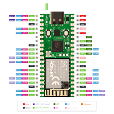
The Elecrow Pico W5 is a third-party development board compatible with the Raspberry Pi Pico ecosystem. Most variants use the RP2040 microcontroller (dual-core ARM Cortex-M0+ @ up to 133 MHz, 264 KB SRAM, 8 MB onboard flash, USB Type-C interface, dual-band Wi-Fi + Bluetooth via an external module such as BW16), while some newer listings mention an RP2350 version. The pinout, GPIO capabilities, PIO blocks, PWM slices, and ADC channels are identical or very closely aligned with the official Raspberry Pi Pico.
All examples below use the official Raspberry Pi Pico C/C++ SDK (compatible with the Pico W5 due to RP2040 compatibility). They are written assuming standard SDK setup with CMake and assume the board behaves like a standard RP2040-based Pico (with USB CDC serial enabled). Onboard LED is typically on GPIO 25.
1. GPIO pin high/low at 1 ms intervals (simple toggle/blink)
#include <stdio.h>
#include "pico/stdlib.h"

int main() {
    const uint led_pin = 25;  // Onboard LED (common on Pico W5 variants)

    stdio_init_all();         // Optional: enables USB serial output

    gpio_init(led_pin);
    gpio_set_dir(led_pin, GPIO_OUT);

    while (true) {
        gpio_put(led_pin, 1);
        sleep_ms(1);
        gpio_put(led_pin, 0);
        sleep_ms(1);
    }

    return 0;
}
CMakeLists.txt snippet (ensure USB stdio if debugging via serial):
pico_enable_stdio_usb(your_project 1)
pico_enable_stdio_uart(your_project 0)
2. Read ADC 20 times per second and append to a file
The RP2040 provides four 12-bit ADC channels (GPIO 26–29 / ADC0–3). No native filesystem exists in bare-metal C SDK mode. This example reads ADC0 (GPIO26) at 20 Hz and prints values over USB serial (view in a terminal at 115200 baud). For actual file appending, integrate an SD card library (e.g., no-OS-FatFS-SD-SPI-RPi-Pico) or log to a host PC.
#include <stdio.h>
#include "pico/stdlib.h"
#include "hardware/adc.h"

int main() {
    stdio_init_all();

    adc_init();
    adc_gpio_init(26);      // ADC0 on GPIO26
    adc_select_input(0);

    while (true) {
        uint16_t value = adc_read();  // 0–4095
        printf("ADC0: %u\n", value);
        sleep_ms(50);                 // 50 ms = 20 samples/second
    }

    return 0;
}
3. PWM example with 5 different duty cycles
PWM is available on most GPIOs via 8 slices (16 channels). This example uses GPIO16 (slice 8, channel A) at ~1 kHz and cycles through 0%, 25%, 50%, 75%, 100% duty.
#include <stdio.h>
#include "pico/stdlib.h"
#include "hardware/pwm.h"

int main() {
    const uint pwm_pin = 16;

    gpio_set_function(pwm_pin, GPIO_FUNC_PWM);

    uint slice = pwm_gpio_to_slice_num(pwm_pin);
    uint chan  = pwm_gpio_to_channel(pwm_pin);

    // ~1 kHz with 125 MHz system clock
    pwm_set_wrap(slice, 124999);
    pwm_set_clkdiv(slice, 1.0f);

    pwm_set_enabled(slice, true);

    const float duties[] = {0.0f, 25.0f, 50.0f, 75.0f, 100.0f};

    while (true) {
        for (size_t i = 0; i < 5; i++) {
            uint level = (uint)((duties[i] / 100.0f) * 125000.0f);
            pwm_set_chan_level(slice, chan, level);
            printf("Duty: %.0f%%\n", duties[i]);
            sleep_ms(2000);
        }
    }

    return 0;
}
4. Output to serial port (USB CDC or UART)
USB CDC (virtual COM port) is the primary method. UART0/1 are also available on GPIO pins.
#include <stdio.h>
#include "pico/stdlib.h"
#include "hardware/uart.h"

int main() {
    stdio_init_all();  // USB CDC → printf goes here

    // Optional: UART0 on GPIO0 (TX), GPIO1 (RX) at 115200 baud
    uart_init(uart0, 115200);
    gpio_set_function(0, GPIO_FUNC_UART);
    gpio_set_function(1, GPIO_FUNC_UART);

    uint32_t counter = 0;

    while (true) {
        printf("USB CDC: Counter = %lu\n", counter);

        // Also send to UART0 if connected
        uart_printf(uart0, "UART0: Counter = %lu\n", counter);

        counter++;
        sleep_ms(1000);
    }

    return 0;
}
CMakeLists.txt (required for USB output):
pico_enable_stdio_usb(your_project 1)
pico_enable_stdio_uart(your_project 0)
5. Clocks on the RP2040 and how to read them
The RP2040 clock architecture includes:
- clk_ref — Reference clock (typically 12 MHz from external crystal, or fallback ring oscillator ~6–12 MHz)
- clk_sys — System clock for cores, bus, most peripherals (default 125 MHz, max ~133 MHz via PLL)
- clk_peri — Peripheral clock (UART, SPI, I2C, PWM; often = clk_sys)
- clk_usb — Fixed 48 MHz for USB PHY
- clk_adc — Fixed 48 MHz for ADC
- ROSC — Internal ring oscillator (unstable, variable)
- XOSC — External crystal oscillator (12 MHz nominal)
- PLL sys / PLL usb — Generate higher/fixed frequencies from reference
Use clock_get_hz() from hardware/clocks.h to read frequencies at runtime.
Example program:
#include <stdio.h>
#include "pico/stdlib.h"
#include "hardware/clocks.h"

int main() {
    stdio_init_all();

    while (true) {
        printf("clk_ref  = %u Hz\n",  clock_get_hz(clk_ref));
        printf("clk_sys  = %u Hz\n",  clock_get_hz(clk_sys));
        printf("clk_peri = %u Hz\n",  clock_get_hz(clk_peri));
        printf("clk_usb  = %u Hz\n",  clock_get_hz(clk_usb));
        printf("clk_adc  = %u Hz\n",  clock_get_hz(clk_adc));
        printf("------------------------\n");

        sleep_ms(2000);
    }

    return 0;
}
Typical default values (stock configuration):
- clk_ref ≈ 12 000 000 Hz
- clk_sys ≈ 125 000 000 Hz
- clk_peri ≈ 125 000 000 Hz
- clk_usb = 48 000 000 Hz
- clk_adc = 48 000 000 Hz
These values remain consistent across RP2040-based boards like the Pico W5 unless custom clock configuration is applied (via set_sys_clock_* functions or overclocking).
If your specific Pico W5 variant uses RP2350 instead of RP2040, or if you require examples adapted for Arduino IDE, MicroPython, or wireless features, please provide additional clarification.